LCR06 Common Rail Injector HEUI EUI EUP Injector ZME SCR Valve Capacitance Resistance Inductance Tester
Product Description
LCR06 Common Rail Injector HEUI EUI EUP Injector ZME SCR Valve Capacitance Resistance Inductance Tester


HW-LCR06 Professional LCR Meter User Manual
1.Product introduction
Intelligent measurement, quality factor, loss factor,
phase angle and equivalent resistance;
Automatic selection of series or parallel measurement mode;
Inductance, Capacitance,Resistance,DC resistance measurement;
Measuring frequency: 100Hz/120Hz/1kHz/10kHz/100kHz;
Battery: 3.7V standard lithium battery/9V alkaline battery can be selected.
External dimension:114×42×223mm;
Measuring range and accuracy:
L:20mH??2000H Highest accuracy (0.5%+5 bit);
C:200pF?--20mF Highest accuracy (0.5%+5 bit);
R:20Ω??--200MΩ Highest accuracy (0.3%+5 bit);
IMP/FREQ
DCR
100/120Hz
1kHz
10kHz
100kHz
0.1-1
1.0%
1.0%
1.0%
1.0%
1.0%
1-10
0.5%
0.5%
0.5%
0.5%
0.5%
10-100k
0.3%
0.3%
0.3%
0.5%
0.3%
100k-1M
0.5%
0.5%
0.5%
1%
1M-20M
1.0%
1.0%
1.0%
20M-200M
2.0%
2.0%
5.0%
Remarks
D≤0.1
Note: If D>0.1 multiply by
Capacitance Conversion Impedance:
Inductance Converted Impedance:
Matters needing attention:
1) Do not use it in flammable and explosive environment, avoid using it in dusty,
direct sunlight, and high-temperature radiation environment;
2) Non professional maintenance personnel are not allowed to open the back cover.
When it is necessary to maintain, replace components and calibrate instruments,
professional personnel should implement or contact relevant dealers and the company`s
after-sales service;
3) Do not disassemble or modify the instrument. Unauthorized modification may
Cause permanent damage to the instrument;
4) When measuring components on the line, please ensure that the power supply of the measuring circuit has been cut off and all capacitors on the circuit have been discharged;
5) It is strictly forbidden to input voltage at the measuring port, and capacitors
and other live components must be discharged before measurement;
6) Four power supply modes: 3.7V lithium battery,9V alkaline battery, USB 5V,
DC Power 9 ~12V,
Only one of 3.7V lithium battery and 9V alkaline battery can be used.
2.Environmental conditions
1) Altitude: <2000 meters
2) Storage humidity: ≤75% RH
3) Working environment: 0℃~40℃
4) Storage environment: -20℃~+50℃
3.Features
1) Measurement frequency: 100Hz/120Hz/1KHz/10KHz/100KHz
2) Measuring voltage: 0.6Vrms
3) Output impedance: 120Ω
4) Basic accuracy: 0.5%
5) LCR automatic recognition/manual measurement
6) DCR DC resistance measurement
7) Open/short calibration compensation
8) Automatic shutdown
9) Lighting lamp
10) Relative measurement and Screening function
4.Description of impedance parameters
Impedance measuring instruments can be divided into DC impedance and AC impedance
according to different measuring signals. Generally, the multimeter measures DC impedance,
and HW-LCR06 digital bridge can measure DC impedance and AC impedance. Impedance is the
most basic parameter for evaluating electronic components and circuit systems. In DC mode,
the resistance of linear two terminal devices is defined by Ohm`s law. In AC mode, the
ratio of voltage to current is complex. An impedance vector includes the real part
(resistance R) and the imaginary part (reactance X). Impedance is expressed in the form of
R+jX in rectangular coordinate system, or amplitude | Z | and phase angle in polar coordinate
system θ The relationship between them is as follows:
Rs = |Zs| cosθ
Xs = |Zs| sinθ
Xs/Rs = tanθ
θ = tan-1(Xs/Rs)
If θ> 0, reactance inductive
If θ< 0, reactance capacitance 5.Measurement mode
Impedance can be measured in series and parallel modes. In parallel mode, impedance Z can
be expressed as mutual admittance of Y.
Y=G+JB, G is conductance and B is admittance.
6.LCD display description
(1) Data hold
(2) Open/Short Calibration
(3) Automatic shutdown
(4) Relative measurement
(5) Main LCD
(6) Sub LCD
(7) Analog bar
(8) Screeninging tolerance mode
Other definitions:
1) LCR: Automatic recognition mode 2) Lp: Inductance parallel measurement mode
3) Ls: Inductance series measurement mode 4) Cp: Capacitance parallel measurement mode
5) Cs: capacitance series measurement mode 6) Rp: resistance parallel measurement mode
7) Rs: resistance series measurement mode 8) DCR: resistance DC measurement mode
9) D: loss factor 10) Q: quality factor
11) θ: Phase angle 12) ESR: Equivalent series resistance
13) ERP: Equivalent parallel resistance 14) DUT: Component under test
15) Short press < 1S (Second), long press > 2S, the duration of pressing the button 7. Front panel key function description
(1) LCD display area
(2) Power LEDs
(3) Frequency selection/
function Screening key
(4) Power switch
(5) LCD backlight/light switch
(6) USB communication function
(7) Secondary parameter
selection function
(8) Enter key
(9) Discharge port-
(10) Test input terminal-
(11) Shield protection terminal
(12) Test input terminal+
(13) Discharge port-
(14) Relative measurement
function
(15) Series/parallel function
(16) Inductance/capacitance/
resistance measurement
selection
(17) Screening measurements
(18) Open/Short Calibration
(19) Auto backlight sensor hole
(20) DC9?12V charging
(21) spare
(22) USB charging
(23) Lighting lamp
8. Operation Guide
1). Automatic measurement:
When the instrument is turned on, the default state is the automatic identification
mode, Auto LCR, and the default frequency is 1KHz. In the automatic mode, the instrument
automatically recognizes the impedance characteristics of the object, and automatically
selects the main parameters and secondary parameters of L, C, R and their appropriate
series-parallel connection method.
The corresponding relationship between the main parameters and the secondary parameters
of the automatic mode is as follows:
Capacitance C Loss Factor D
Capacitance L quality factor Q
Capacitance R phase angle θ
In the automatic measurement mode, the series-parallel connection method depends on the
impedance of the measured object. When the impedance is high (>10KΩ), the parallel
connection method is automatically selected, and when the impedance is low (<10KΩ), the
series connection method is automatically selected.
2). Data Hold
Press the "HOLD" key for a long time during the measurement to enter the data holding, and the LCD displays the data holding symbol "HOLD". Press the "HOLD" key again to exit
the data holding and return to the normal measurement mode.
3). L/C/R mode measurement parameters
Manual L/C/R mode selects the corresponding parameters.
1) Main parameter selection, in the power-on state, the default is AUTO LCR, press
the "FUNC" key,cycle selection"ATUO LCR"-"ATUO L"-"ATUO C"-"ATUO R"-"DCR"? "ATUO LCR".
2) For sub parameter selection, press "SER/PAL" key in the corresponding main
parameter measurement mode to switch the series/parallel measurement mode, and press
"D.Q θ” Key to select sub parameters "D", "Q"“
θ”、 "ESR" (Note: if the series
measurement mode is "ESR" and the parallel measurement mode is "RP",)
The sub parameters cannot be set in "AUTO R" or "AUTO DCR" mode.
① Measure the capacitance in the "AUTO LCR" mode. If the capacitance value is<5pF,
the equivalent parallel resistance Rp is used to replace the D loss factor for the sub
parameter;
② When entering the "AUTO R" or "AUTO DCR" measurement in the "AUTO LCR" mode,
some sub parameters will not be displayed on the LCD.
4). Measurement frequency
HW-LCR06 provides 5 frequency test points, 100Hz/120Hz/1KHz/10KHz/100KHz, the default
frequency is 1KHz when starting up, press the "FREQ" button to select different frequency
points for measurement.
Note: "AUTO DCR" mode is DC impedance measurement, the measurement frequency is
ignored.
5). Deviation ratio setting
The deviation setting is used to compare the deviation ratio of two components. The
main display is the main value of the tested component, and the secondary display is the
deviation percentage. The LCD main display value is automatically recorded as the nominal
value.
Percentage display range: -99.9%~99.9%
The displayed percentage is:
REL%=( DCUR-DREF)/DREF*100%
DCUR: the main parameter value of the component under test
DREF: Nominal value entered
If DCUR >2DREF or 2DCUR < DREF, the secondary display is "0L%", and the main display is the
main parameter value of the component under test.
(1) Entry deviation measurement
Press the "FUNC" key to select the appropriate mode, "AUTO L", "AUTO C", "AUTO R"
or "AUTO DCR", and confirm the tested
The terminal has been connected to the measured component, press the "REL" key to
enter the deviation proportion measurement mode, and the LCD will display“
Δ” Symbol.
The main display is the main parameter value of the tested component, and the secondary
display displays the percentage deviation in percentage. Press the "REL" key again, the
main display will display the nominal value on the LCD“
Δ” The symbol flashes and the
sub display shows the percentage deviation. Press the "REL" key again to return to the
normal deviation measurement mode.
(2) Exit deviation measurement
Long press the "REL" key to exit the deviation measurement and return to the normal
mode. 6). Screening measurements
The screening measurement mode is used to quickly screen components whose main
parameters are within a certain range. Press the "FUNC" key to select the appropriate
mode, "AUTO L", "AUTO C", "AUTO R" or "AUTO DCR". Confirm that the test terminal has been
connected to the tested component. Long press "FREQ" for about two seconds, release the
key to enter the Screeninging mode, and the LCD will display the "Sorting" symbol. The main
display is "PASS", and the secondary display displays the main value of the tested
component and enters the nominal value.Replace the tested element. If it is within the
screening limit, the main display will display "PASS", the secondary display will display
the main value of the tested element, and the buzzer will ring once Limit range: the main
display "FAIL" and the secondary display display the main value of the tested element.
(1) Screening range setting
Screening limit mode can be set as: ±0.25%, ±0.5%, ±1%, ±2%, ±5%, ±10%, ±20%,
+80%~-20%.The default range is ±1%. In the main screening mode, press the "SETUP" button
to enter the setting, the "Range" symbol on the LCD will flash, press "ENTER" to confirm
and enter the main parameter value setting, the last digit of the main parameter on the
LCD will flash, Press the "
" key to decrease the value one by one, press the "
" key
to increase the value one by one, press the " " key to move the flashing position of the
main parameter to the right, and press the " " key to move the flashing position of the
main parameter to the left, and the corresponding value can be adjusted , press the
"Enter" key to enter the Screening range setting, the "TOL±1%" symbol on the LCD flashes,
press the " " or " " key to adjust the Screening range value, press "ENTER" to confirm
the setting, and then the component can be screened Measurement.
(2) Exit Screening mode
Press the "Sorting" key to exit the sorting measurement mode and return to the normal
mode.
7). Calibration function
The calibration function can effectively reduce the distributed parameter interference
caused by the test line. The calibration function includes short circuit calibration and
open circuit calibration. The short circuit calibration can reduce the impact of contact
resistance and test line resistance on the measurement of low impedance components; Open
circuit calibration can reduce the influence of the distributed capacitance and resistance
of the test line on the measurement of high impedance components.
(1) Enter the calibration function
Start up and long press the "CAL" key to enter open circuit calibration. The LCD sub
display displays
. Then press the "CAL" key to start calibration. The LCD displays a
30 second countdown. When the countdown reaches 0, the LCD displays
.


It indicates that the open circuit calibration is completed. Press the "CAL" key, the
LCD sub display displays
, insert the probe, short-circuit the clamp, and press the "CAL"
key to open At the beginning of calibration, the LCD displays a 30 second countdown. When the
countdown reaches 0, the LCD displays
, indicating that the short circuit calibration
is completed, and then press the "CAL" key to return to the normal test mode.
Note: Open circuit calibration if LCD displays
, It indicates that the
calibration failed. Check whether the test terminal is in open circuit state, and
ensure that the open circuit is calibrated again.
Short circuit calibration If the LCD displays
, it indicates that the
calibration has failed. Check whether the clip is short circuited? After confirming the
short circuit, calibrate again.
(2) Exit calibration function
After calibration, press the "CAL" key briefly to exit the calibration function.
8). Backlight
Short press the "BKLIT" button to turn on the LCD backlight, short press the "BKLIT"
button again to turn off the LCD backlight,If there is no operation, the backlight will
be automatically turned off after 60 seconds.
Long press the "BKLIT" button to turn on the top lighting, long press the "BKLIT"
button again to turn off the top lighting.
9). Automatic shutdown
If there is no operation, after 5 minutes, the beep will beep twice every 5 seconds,
and after three beeps, it will automatically shut down.
9.Quick Application Guide
1). Series/parallel mode selection
More accurate measurement data can be obtained by selecting an appropriate equivalent
mode, and the series equivalent mode should be selected for low impedance components (such as
less than 10K Ω);Parallel equivalent mode should be selected for high impedance components
(such as less than 10K Ω).
2). Inductance measurement
(1) Press
to power on;
(2) Press the "FUNC" key, "Lp" will be displayed on the LCD, and select the inductance
measurement gear;
(3)Insert the inductance into the test port or connect the measured inductance with
corresponding accessories;
(4) Press the "FREQ" button to select the appropriate test frequency;
(5) Press "D/Q/θ" to select the secondary parameters to be tested. 3). Capacitance measurement
Warning! The capacitance must be completely discharged before measurement
(1) Press
to power on;
(2) Press the "FUNC" key, "Cp" will be displayed on the LCD, and select the capacitance
measurement gear;
(3)Insert the capacitance into the test port or connect the measured capacitance with
corresponding accessories;
(4) Press the "FREQ" button to select the appropriate test frequency;
(5) Press "D/Q/θ" to select the secondary parameters to be tested.
4). Resistance measurement
(1) Press
to power on;
(2) Press the "FUNC" key, "Rp" will be displayed on the LCD, and select the resistance
measurement gear;
(3)Insert the resistance into the test port or connect the measured resistance with
corresponding accessories;
(4) Press the "FREQ" button to select the appropriate test frequency;
(5) Press "D/Q/θ" to select the secondary parameters to be tested.
5). DC impedance measurement
(1) Press
to power on;
(2) Press the "FUNC" key, "DCR" will be displayed on the LCD, and select the DC
resistance measurement gear;
(3)Insert the resistance into the test port or connect the measured resistance with
corresponding accessories;
Note: DC resistance measurement frequency and sub parameters are ignored, and LCD
does not display sub parameters.
10. Technical indicators
Precautions
1) Test environment temperature: 23°C±5°C, humidity: ≤75% R.H.
2) Warm up for 10 minutes before testing;
3) Test on the instrument port slot;
4) Open/short calibration before testing;
5) If the actual measurement and display range of the instrument exceeds the range
indicated in the table, the accuracy is not specified for the measured value beyond the
range in the table. Note: This accuracy is evaluated when D<0.1, if D>0.1,
(Ae is the accuracy)
Note: This accuracy is evaluated when D<0.1, if D>0.1,
(Ae is the accuracy) Note: This accuracy is evaluated when D<0.1, if D>0.1,
(Ae is the accuracy)
11. Replace the battery
Warning
When symbols appear
on the LCD display screen, charge or replace the battery in time,
otherwise the measurement accuracy will be affected.
12. Frequently asked questions
If the instrument cannot be turned on, please follow the steps below to start checking:
1) Check whether the battery voltage is normal? 3.7V lithium battery should be about 3.7V,
9V alkaline battery should be greater than 9V;
2) Whether the external power supply and its power input socket are normal;
3)
Are the buttons not working?
If the measurement result is abnormal, please start the inspection as follows:
1) Is the spring piece in the test port in good contact with the element pin?
2) Check whether the test line is in good condition;
3) If the problem still cannot be solved, please contact the dealer
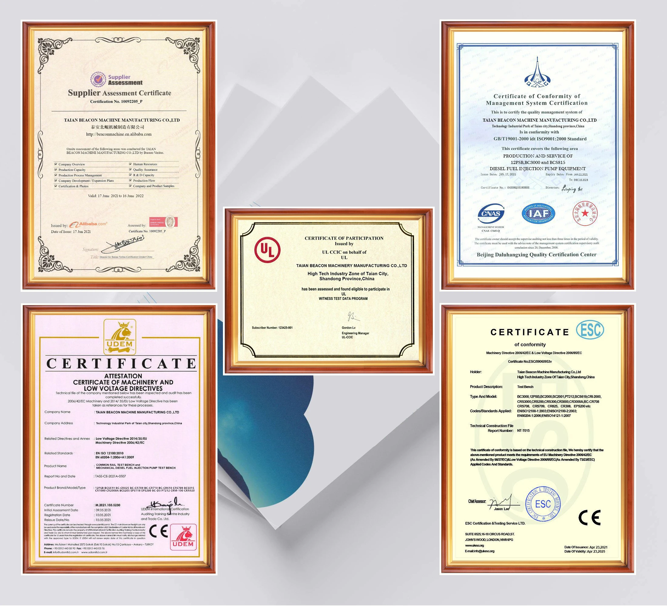
Certification
Customer Feedback

Customer Photos


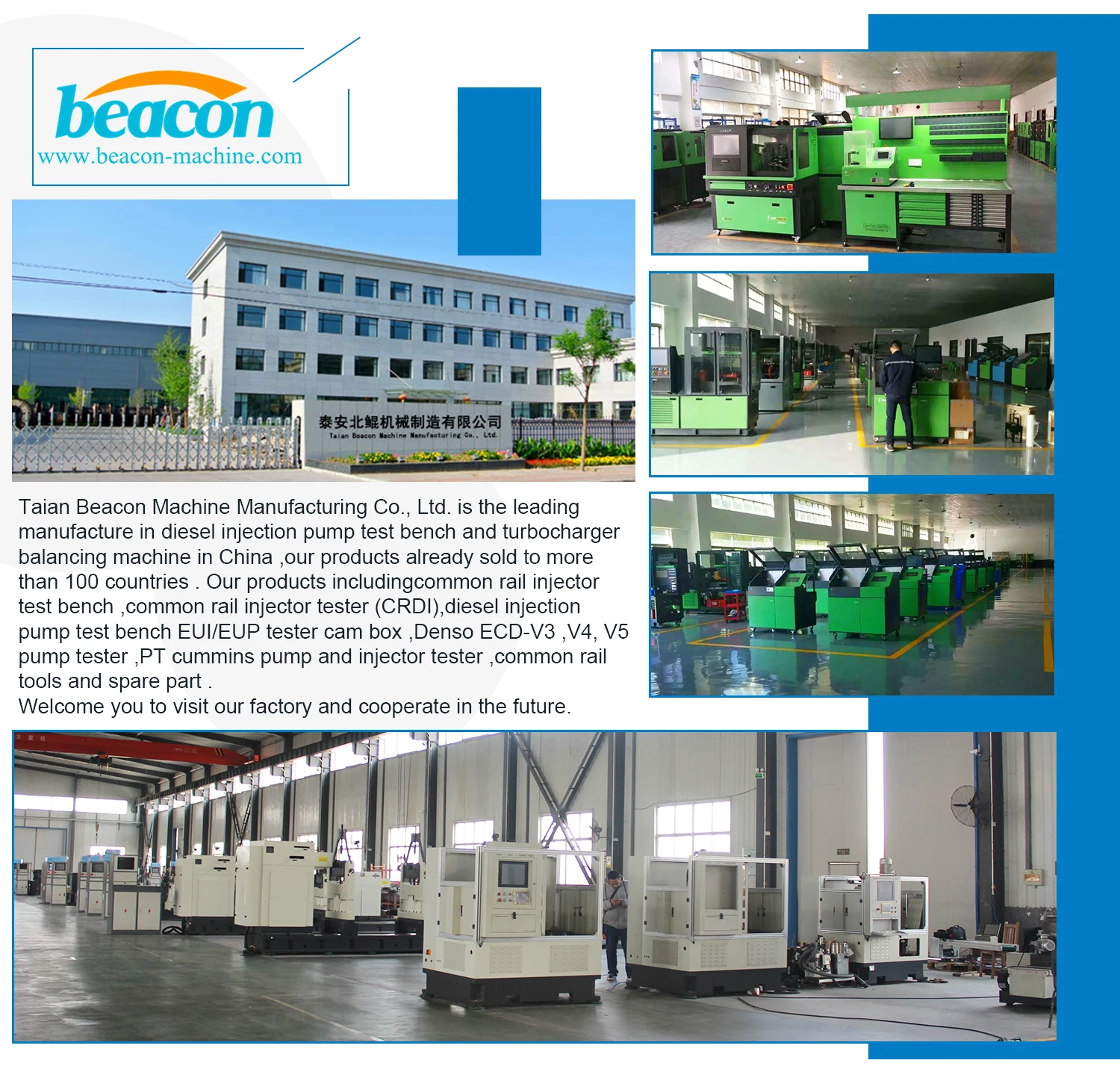
Company Profile
Contact Us


 배송기간
배송기간